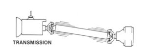
TECH TALK: A LITTLE INFORMATION ABOUT DRIVELINE VIBRATION
Vibration in a driveshaft can occur from many different sources, let’s take a look at these now.
One of the most common causes of driveline vibration is worn U-joints or slip splines, out-of-balance components yokes out of phase or at misaligned angles, and yoke ears that are not concentric with the splines
This is especially noticeable when approaching the critical speed range.
Vibration problems must be diagnosed accurately and corrected quickly to avoid damage to the driveline components.
It is often difficult to determine if a vibration of the vehicle is coming from the driveshaft or something else.
Here are some things to think about while you are troubleshooting any driveshaft problem.
First, Second, and Third Order Driveshaft Vibrations
It’s important to know the difference when troubleshooting your vibration.
A First-order driveshaft vibration will cause a single shake or disturbance for each revolution of the driveshaft.
IMPORTANT: Anything that is out of balance will only cause the first-order vibration, never any higher-order vibrations.
First-order driveshaft vibration is usually caused by:
- A component rotating the same speed as the driveshaft that is out-of-round.
- A component rotating the same speed as the driveshaft that is out-of-balance.
- Drive axle problems.
- Driveshaft balance issues can generally be felt at vehicle speeds over 30mi./h
A Second-order driveshaft vibration will cause two shakes or disturbances for each revolution of the driveshaft.
IMPORTANT: A component that is out of balance will NEVER cause a second or higher-order vibration, only a first-order vibration.
Second-order driveshaft vibration is usually caused by:
- Incorrect or altered Vehicle Trim Height
- Powertrain Mounting Problems from either incorrect or misaligned
- Failed or Failing U-Joints
- Improperly phased or twisted driveshafts
- Improper driveshaft angles. Driveshaft angle problems can be felt at very low speeds and higher speeds
- Drive Axle Problems
Third-order driveshaft vibration will cause three shakes or disturbances for each revolution of the driveshaft.
This type of vibration is very rare and will not be present on vehicles with Cardan U-joints.
IMPORTANT: A component that is out of balance will NEVER cause a third or higher-order vibration, only a first-order vibration.
Third-order driveshaft vibrations are usually caused by:
- Failed, failing, or binding Constant Velocity (CV) Joints.

– Remove the driveshaft and rotate the CV joint through its full range of motion while feeling for any rough spots or looseness.
If the component is perfectly balanced, rotation creates centrifugal force equal in all directions from the center of rotation.
The imbalance creates an unequal centrifugal force, resulting in an excessive “pull” toward the heaviest point on the component. Imbalance can be caused by excessive weight at one point,
a lack of weight at one point, or a bent or dented shaft. Imbalance also creates vibration during the rotation of the driveshaft.
.………….
Most materials have a natural frequency, just as each string on a guitar has its own tone. The natural frequency of tubing material results in a particular critical speed for that shaft, based on its length, diameter, thickness, and composition.
As the tubing approaches critical speed, the tubing will begin to vibrate.
Critical Speed Is the RPM at which the driveshaft is a computer projected to bend or whip.
Exceeding Critical Speed can produce vibrations that can result in driveshaft failure.
At critical speed, Driveshaft length, engine rpm, and transmission gearing must be considered when selecting a driveshaft.
To check for critical speed, calculate this equation:
Top speed x 336 (a constant) x rear ratio (like 4.10), then divide it by the tire height (28” tall tire).
Here is an example:
Top speed is 160mph x 336 = 53760 x rear ratio of 4.10 = 220416, then divide this number by the tire height, 28”… This car would have a top RPM of 7872.
Now the shaft is designed will need to be able to so this RPM.
Sample Critical Speed Chart
|
Driveshaft Center to Center Length |
|||||||||
|
40” |
42” | 44” | 46” | 48” | 50” | 52” | 54” |
56” |
|
| Mild Steel | |||||||||
| 3” x 0.83 |
10,500 |
10,000 | 9,000 | 8,200 | 7,000 | 6,900 | 6,400 | 5,900 |
5,400 |
| 3.5” X 0.83 |
10,700 |
10,500 | 9,700 | 8,700 | 8,000 | 7,400 | 6,800 |
6,300 |
|
| 4” X 0.83 |
10,500 |
9,800 | 9,500 | 8,800 | 8,000 |
7,600 |
|||
| Chromoly | |||||||||
| 3” x 0.83 |
10,500 |
10,000 | 9,000 | 8,200 | 7,000 | 6,900 | 6,400 | 5,900 |
5,400 |
| 3.5” X 0.83 |
10,700 |
10,500 | 9,700 | 8,700 | 8,000 | 7,400 | 6,800 |
6,300 |
|
| Aluminum | |||||||||
|
3.5” x .125 |
11,000 |
10,800 | 10,650 | 9,800 | 8,800 | 8,100 | 7,500 | 6,900 |
6,400 |
|
10,850 |
9,900 | 9,600 | 8,900 | 8,100 |
7,700 |
||||
| Carbon Fiber | |||||||||
| 3.75” x 120 |
14,500 |
13,800 | 12,400 |
11,500 |
|||||
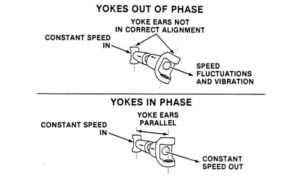
PHASING
Phasing is the correct alignment between yokes at each end of the shaft. If the yokes are not in phase, speed fluctuations will not be canceled out.
These fluctuations cause vibration, which may damage components on the engine and the Jet pump.
On most applications, the yokes are commonly in a phase when the yoke ears are parallel to each other.
Sections of the shaft assembly have line-up arrows to assist in phasing.
Hover over the image to enlarge

To check for critical speed, calculate this equation:
Top speed x 336 (a constant) x rear ratio (like 4.10), then divide it by the tire height (like 28” tall tire).
Here is an example:
Top speed is 160mph x 336 = 53760 x rear ratio of 4.10 = 220416, then divide this number by the tire height, 28”.
This car would have a top RPM of 7872. Now the shaft is designed will need to be able to so this RPM.
TECH VIDEO: Diagnosing Wheel-Hop Axle-Wrap & Driveline Vibration
Please log in to leave a comment.
No Comments Yet